
 Business License

Copper bar specifications for American standard medium voltage armored switchgear
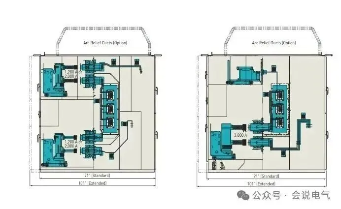
American standard medium voltage armored switchgear, with standard current specifications of 1200, 2000, 3000, 4000A, upper and lower double-layer circuit breaker handcart, and busbar located in the middle of the rear cabinet.
The upper circuit breaker leads out from the upper part of the rear cabinet, and the cable is connected to the copper busbar through the lower vertical channel to the upper part. The incoming and outgoing lines of the lower circuit breaker are directly connected to the bottom plate.
Due to the arrangement of double-layer circuit breakers, the heat generated by the lower circuit breaker will be transmitted to the upper circuit breaker. Ventilation holes are not allowed between high-voltage compartments, and the upper limit of temperature rise in the American standard is 10k lower than that in the IEC standard. Therefore, a large cross-sectional area of copper bars is required.
According to the standard, for continuous current (temperature rise) tests, copper bar specifications are as follows: 1200A uses one 6.4 × 102=652.8mm2 copper bar, and domestic copper bar specifications can be selected as 6 × 100mm; 2000A uses two 9.5 × 102mm copper bars, with a cross-sectional area of 2 × 9.5 × 102=1938mm2, and domestic copper bar specifications can be selected as 2 pieces of 10 × 100mm; 3000A uses three 9.5 × 127mm copper bars, with a cross-sectional area of 3 × 9.5 × 127=3619.5mm2, and domestic copper bar specifications can be selected as 3 pieces of 10 × 125mm; 4000A uses four 9.5 × 127mm copper bars, with a cross-sectional area of 4 × 9.5 × 127=4826mm2.
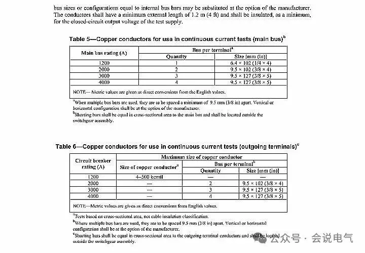
It can be seen that copper bars have large specifications, especially for high current switchgear.
Therefore, for the main busbar of the switchgear, it is necessary to refer to the specifications of the test busbar. Considering the connection of the upper and lower branch busbars, a wide busbar should be used, that is, the upper and lower branch busbars should be overlapped by half, such as a 150mm wide busbar, with half of the upper and half of the lower branch busbars used for busbar overlap.
For 1200A, a 6 × 150mm copper busbar is used, for 2000A, a 12 × 150mm copper busbar is used, for 3000A, two 12 × 150mm copper busbars are used, and for 4000A, three 10 × 150mm copper busbars are used.
Branch busbar, with double-layer circuit breaker arrangement of 2000A and below. 80mm wide copper bars can be used for the upper and lower branch busbars, that is, 1200A with one 10 × 80mm copper bar, and 2000A with two 10 × 80mm or two 10 × 100mm copper bars (determined according to the temperature rise test). For 3000A, two 10 × 150mm copper bars can be used, while for 4000A, which is the same specification as the main busbar, three 10 × 150mm copper bars can be used.
According to IEEE C37.20.2, the busbar needs to be fully insulated, and connections and other parts need to be wrapped with insulating tape or insulation boxes. The insulation layer of the busbar needs to undergo combustion tests to verify its flame retardant performance, as well as insulation performance tests. To meet the test requirements, the surface of the busbar is generally treated with epoxy fluidized insulation, with a fluidized thickness generally greater than or equal to 2mm.
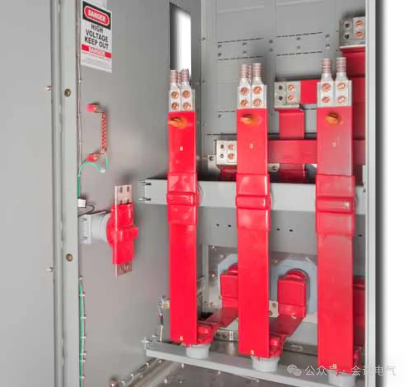
Due to the fully insulated busbar system, the air clearance and creepage distance of the switchgear can be significantly reduced. The air clearance for the 95kV impulse withstand voltage corresponding to the 15kV voltage level is generally required to be greater than 3 inches (3 × 25.4=76.2mm). The power frequency withstand voltage of 36kV generally requires a creepage distance greater than 6 inches (6 × 25.4=152.4mm).
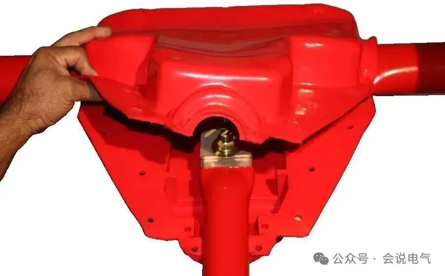
The 15/27kV armored switchgear generally has a phase spacing of 10 inches, or 254mm, regardless of the current size. Therefore, for a 150mm wide branch busbar, removing the insulation layer thickness of 254-150-2-2=100mm fully meets the insulation requirements.
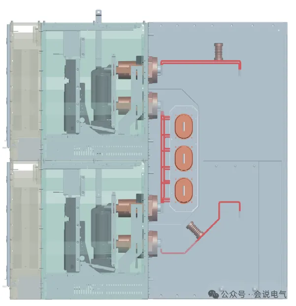
The spacing between the main busbars is generally 280mm. Even after removing the width of the busbars and the distance occupied by the connections, the insulation requirements can still be met.
38kV insulated busbar system. The cabinet width is 42 inches (42 × 25.4=1066.8mm), with a phase spacing of 11 inches (11 × 25.4=279.4mm). The 3000A branch busbar specification uses three 10 × 100mm copper bars, and the air insulation net distance is 279-100-4=175mm, meeting the requirements of fluidized insulation net distance. To improve the current carrying capacity, the new American standard 38kV switchgear adopts tubular busbars, which can increase the current carrying capacity without increasing the net distance.
Recently Posted
-
UL347 standard switchgear
September 24, 2026Many domestic manufacturers claim to comply with UL347 standards by using mid mounted cabinets, especially the 38kV circuit breake Read More
 -
Electrical clearance requirements for North American switchgear
September 24, 2026Many manufacturers may ask if the American standard for switchgear does not specify a minimum electrical clearance. So, what stand Read More
 -
Atmospheric correction of insulation withstand voltage test values for North American switchgear
September 22, 2026The insulation test of the North American medium voltage air insulated armored switchgear standard IEEE C37.20.2 follows the IEEE Read More
 -
Application of Medium Voltage Switchgear for Low Voltage Transformers
September 21, 20261. What is a low-voltage through core current transformer?The function of a current transformer (CT) is to convert high current in
Read More

Contact Us
Recommended Products
-
 Single Phase Oil Immersed Transformer 10KVA 15KVA 25KVA 37.5KVA Standard CompliantNegotiableMOQ: 2 Units
 -
Electrical Arc Furnace Transformers up to 120MVA - Certified for Steel Industry ApplicationsUS$ 8000 - 10000MOQ: 1 Unit
-
3-Phase Oil Type Transformer 5-Year Warranty With Load Test ReportUS$ 5428 - 5628MOQ: 1 Unit
-
Three Phase Oil Filled Transformer for Mining Operations Dust-Proof DesignUS$ 5428 - 5628MOQ: 1 Unit
-
HV Three Phase Oil Filled Transformer With ONAN Cooling 500kVA-2500kVAUS$ 5428 - 5628MOQ: 1 Unit
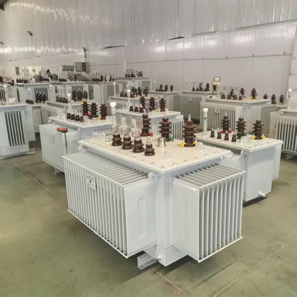
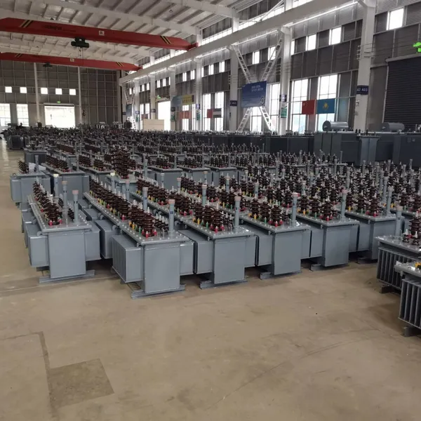
-
11/24/33KV High Voltage Isolation Switch With Mill Test ReportUS$ 800MOQ: 1 Unit
-
3-Pole Outdoor Isolation Switch With 5-Year Warranty and Compliance TestingUS$ 800MOQ: 1 Unit
-
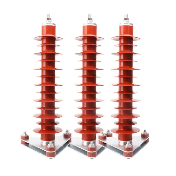
YH5WZ 3KV-110KV Zinc Oxide Arrester for Power Station Outdoor High Voltage DistributionUS$ 21MOQ: 100 Units
-
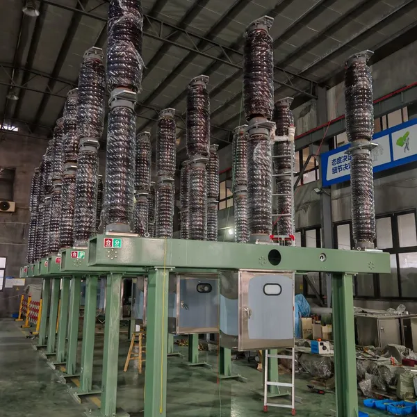
Outdoor SF6 Load Break Switch LW30-72.5/1250A 24KV 630A 16KA Three PhaseUS$ 10000MOQ: 1 Unit
-
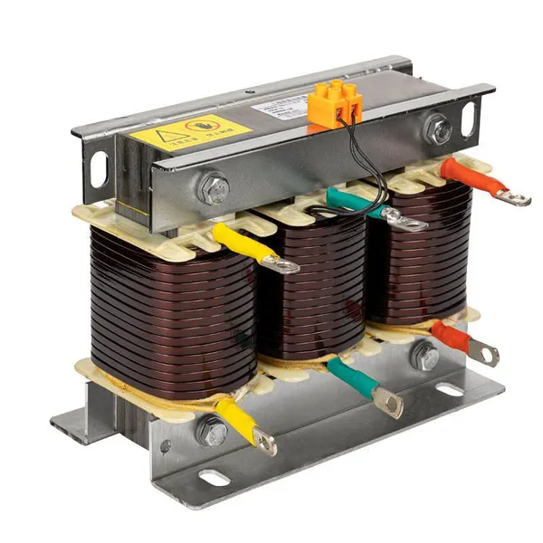
Input Line Reactor for CNC Machine Frequency Converters, 400V 60HzUS$ 65MOQ: 5 Units
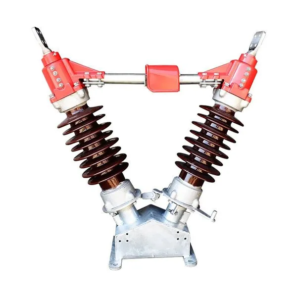
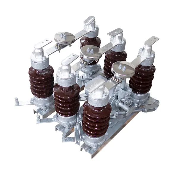
-
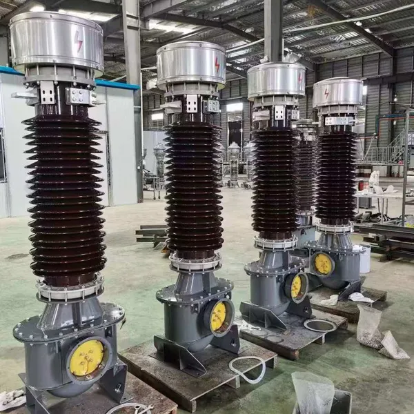
Industrial Grade 35-220KV Oil-Immersed Current Transformer for SubstationsUS$ 480 - 500MOQ: 3 Units
-
LZZBJ9-20 Indoor 24kV High Voltage Cabinet Single-Phase 5-20 for Industrial Power SystemsUS$ 250MOQ: 3 Units
-
17.5 KV Full-enclosed Outdoor Epoxy Resin Casting and Double Pole Insulated Voltage TransformerUS$ 90 - 100MOQ: 1 Piece
-
Three Phase 30kVA SVC Voltage Regulator for Textile Manufacturing, Stable OutputUS$ 159MOQ: 10 Units
-
Amorphous Core 25kVA Transformer Compliant With IEC Standards for Power DistributionUS$ 1300 - 2900MOQ: 2 Units
-
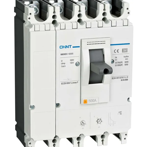
CHINT NM8NDC-630 DC 1000V/Ui High-Voltage Circuit Breaker With 630A Frame CurrentUS$ 425 - 625MOQ: 100 Units
-
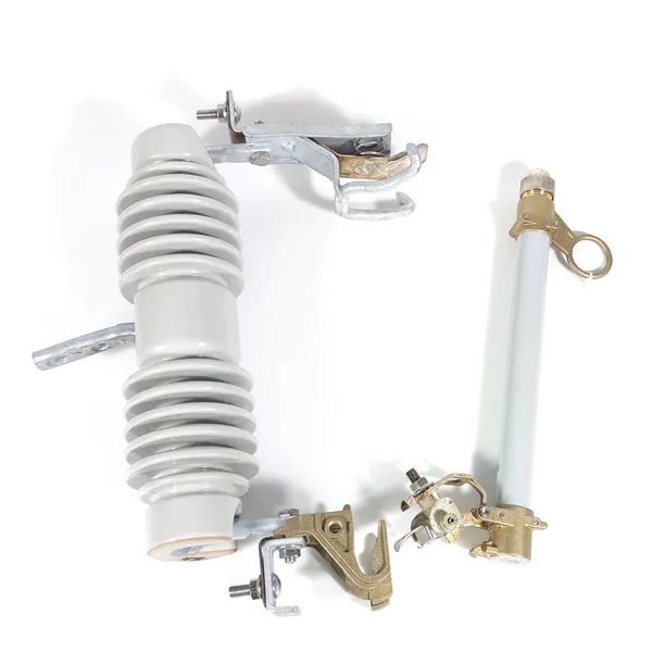
High Voltage Drop Out Fuse Cutout 33KV 27KV 24KV for Overhead LinesUS$ 35MOQ: 100 Units
-
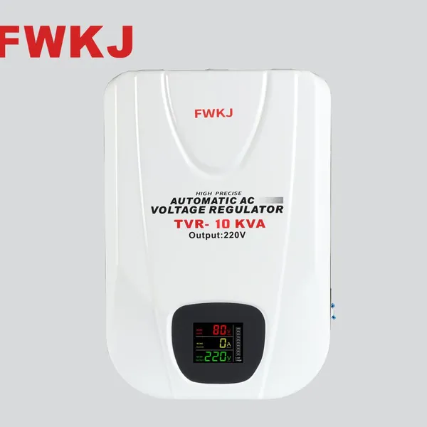
TVR-10 KVA Automatic Voltage Stabilizer 220V ±0.5% Accuracy for Laboratory InstrumentsUS$ 103 - 123MOQ: 1 Unit
-
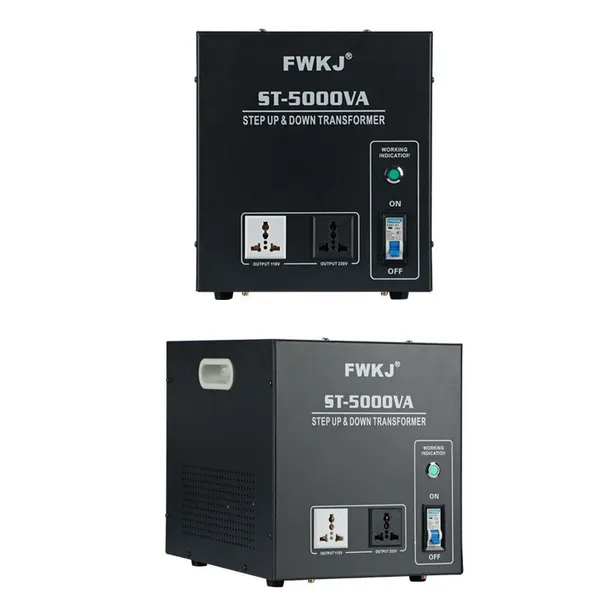
Universal 5000VA Voltage Transformer for International Appliances 110V-220VUS$ 102 - 107MOQ: 10 Units
-
500kV Three-Phase Oil-Immersed Auto Transformer 250MVA for Power GridsUS$ 800 - 9000MOQ: 1 Unit