
 Business License

Why do 99% of CT scans use depolarization?
As the "eyes" of the power system, the polarity determination of current transformers (CTs) can be regarded as a fundamental skill in the field of electrical engineering. This seemingly simple concept actually hides a mystery - it not only concerns measurement accuracy, but also directly affects the reliability of relay protection devices. Today, let's break it apart and explain it clearly!
1、 Scientific definition of polarity
The requested CT polarity essentially describes the phase relationship of the electromotive force of the primary/secondary winding under the action of alternating magnetic flux. When the iron core is excited by the same magnetic field, if both sides of the coil have high or low potential ends at the same time, these corresponding points are called "same polarity ends". Just like the telepathy of twins, their voltage fluctuations always maintain synchronous rhythm.
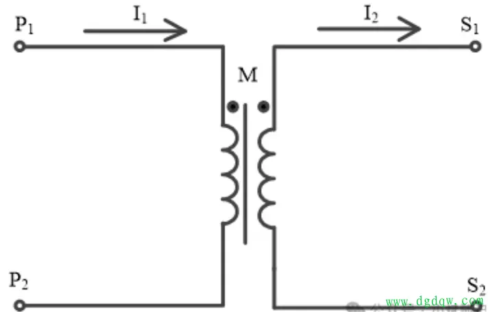
2、 Standardized markings P1-P2 and S1-S2
Industry standards have already paved the way for us: the first and last ends of the side are marked as P1 (incoming end) and P2 (outgoing end) respectively; The secondary side corresponds to S1 and S2. The key point is that when a current flows in from P1 and triumphantly exits through P2, the secondary side must be driven out by S1 and eventually merge into S2. This ingenious arrangement ensures that the magnetic flux direction generated by the two windings is completely consistent, forming a textbook level "depolarization" configuration. And reverse operation? That's the easily confused 'polarity'.
3、 Why are 99% of scenes using depolarization?
Don't think this is done casually! When using depolarization design, the magnetic fields of the main and auxiliary windings cancel each other out instead of overlapping, which can effectively suppress the risk of saturation. Imagine two
The stable structure of stock power sumo wrestling competition while maintaining dynamic balance is the cornerstone of the safe operation of the power system. Unless required by special working conditions, the industry
Choose a polarity reduction scheme for all colors.
4、 The three-step verification method ensures that everything is foolproof
1. Check the identification: strictly compare the P1/S1 markings on the nameplate
2. Phase measurement: Use an oscilloscope to capture the phase difference between the waveforms on both sides
3. Logic verification: Observe whether the protection device operates as expected when powered on. Remember that incorrect polarity connections may cause differential protection to malfunction or refuse to operate, with unimaginable consequences!
5、 The fatal cost of polarity error
There was once a real case: a substation had its CT polarity reversed, causing the differential protection of the line to trip due to misoperation when there was a fault outside the area. This accident caused a large area
Power outage, direct economic losses exceeding one million! It can be seen that the small polarity markings affect the safety nerves of the entire power grid.
Recently Posted
-
Atmospheric correction of insulation withstand voltage test values for North American switchgear
September 22, 2026The insulation test of the North American medium voltage air insulated armored switchgear standard IEEE C37.20.2 follows the IEEE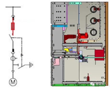 Read More
 -
Application of Medium Voltage Switchgear for Low Voltage Transformers
September 21, 20261. What is a low-voltage through core current transformer?The function of a current transformer (CT) is to convert high current in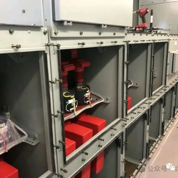 Read More
 -
High voltage current limiter
September 21, 2026High voltage current limiter is a special type of current limiting fuse that meets the high current application requirements diffe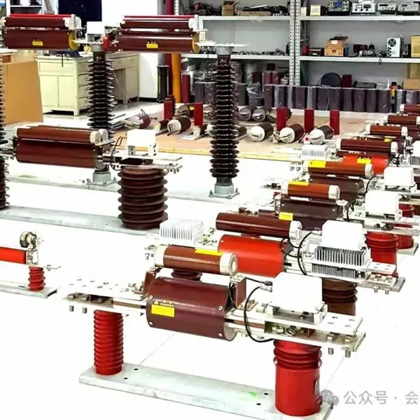 Read More
 -
Medium voltage MCC motor control cabinet
September 17, 2026Regarding the arcing of medium voltage FC switchgear, F-C refers to the combination of contactor and fuse. FC is mainly used for motor protection, and the contactor has a long electrical life of at least 300000 times, suitable for frequent operation. Fuses are used for overload protection. FC is widely used in steel mills, chemical plants, coal-fired power plants, ships, and offshore oil platforms. In these situations, the shRead More

Contact Us
Recommended Products
-
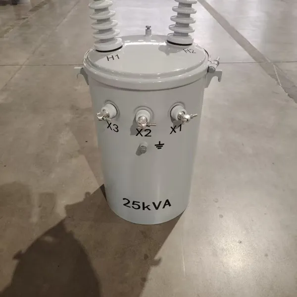
 Single Phase Oil Immersed Transformer 10KVA 15KVA 25KVA 37.5KVA Standard CompliantNegotiableMOQ: 2 Units
 -
Electrical Arc Furnace Transformers up to 120MVA - Certified for Steel Industry ApplicationsUS$ 8000 - 10000MOQ: 1 Unit
-
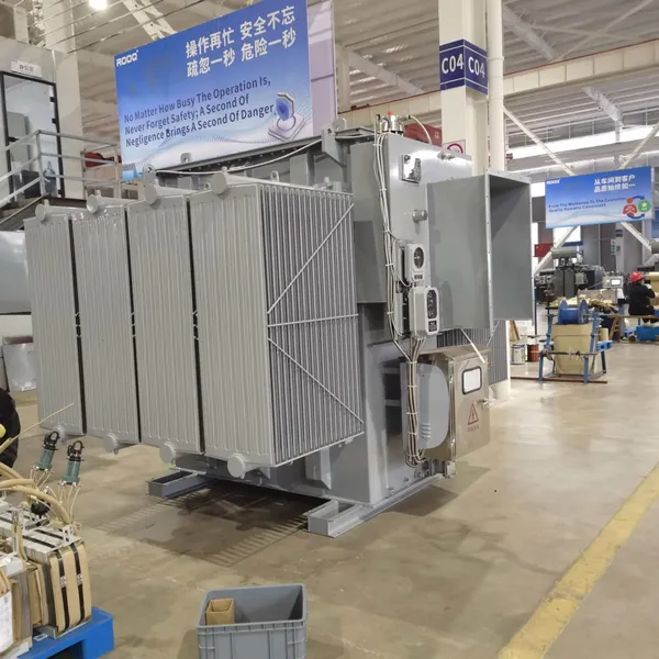
3-Phase Oil Type Transformer 5-Year Warranty With Load Test ReportUS$ 5428 - 5628MOQ: 1 Unit
-
Three Phase Oil Filled Transformer for Mining Operations Dust-Proof DesignUS$ 5428 - 5628MOQ: 1 Unit
-
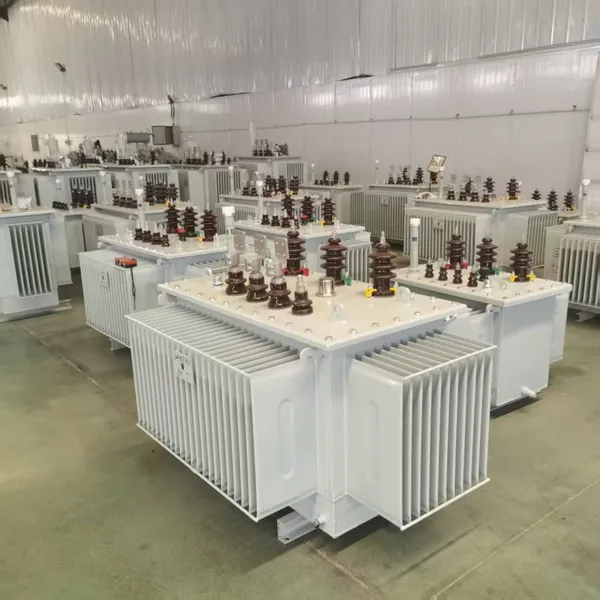
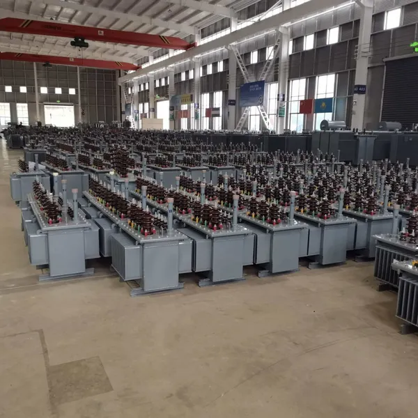
HV Three Phase Oil Filled Transformer With ONAN Cooling 500kVA-2500kVAUS$ 5428 - 5628MOQ: 1 Unit
-
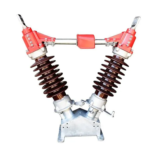
11/24/33KV High Voltage Isolation Switch With Mill Test ReportUS$ 800MOQ: 1 Unit
-
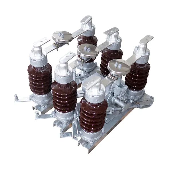
3-Pole Outdoor Isolation Switch With 5-Year Warranty and Compliance TestingUS$ 800MOQ: 1 Unit
-
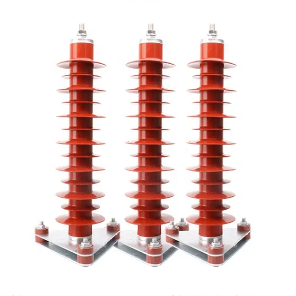
YH5WZ 3KV-110KV Zinc Oxide Arrester for Power Station Outdoor High Voltage DistributionUS$ 21MOQ: 100 Units
-
Outdoor SF6 Load Break Switch LW30-72.5/1250A 24KV 630A 16KA Three PhaseUS$ 10000MOQ: 1 Unit
-
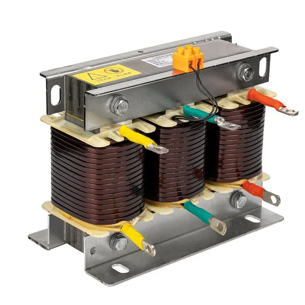
Input Line Reactor for CNC Machine Frequency Converters, 400V 60HzUS$ 65MOQ: 5 Units
-
Industrial Grade 35-220KV Oil-Immersed Current Transformer for SubstationsUS$ 480 - 500MOQ: 3 Units
-
LZZBJ9-20 Indoor 24kV High Voltage Cabinet Single-Phase 5-20 for Industrial Power SystemsUS$ 250MOQ: 3 Units
-
17.5 KV Full-enclosed Outdoor Epoxy Resin Casting and Double Pole Insulated Voltage TransformerUS$ 90 - 100MOQ: 1 Piece
-
Three Phase 30kVA SVC Voltage Regulator for Textile Manufacturing, Stable OutputUS$ 159MOQ: 10 Units
-
Amorphous Core 25kVA Transformer Compliant With IEC Standards for Power DistributionUS$ 1300 - 2900MOQ: 2 Units
-
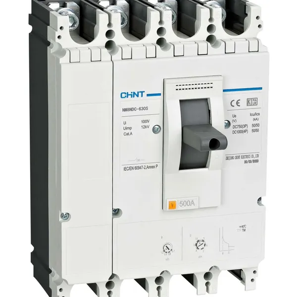
CHINT NM8NDC-630 DC 1000V/Ui High-Voltage Circuit Breaker With 630A Frame CurrentUS$ 425 - 625MOQ: 100 Units
-
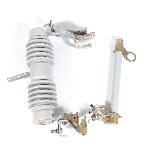
High Voltage Drop Out Fuse Cutout 33KV 27KV 24KV for Overhead LinesUS$ 35MOQ: 100 Units
-
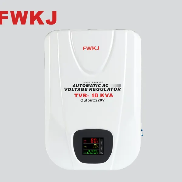
TVR-10 KVA Automatic Voltage Stabilizer 220V ±0.5% Accuracy for Laboratory InstrumentsUS$ 103 - 123MOQ: 1 Unit
-
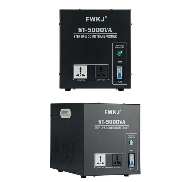
Universal 5000VA Voltage Transformer for International Appliances 110V-220VUS$ 102 - 107MOQ: 10 Units
-
500kV Three-Phase Oil-Immersed Auto Transformer 250MVA for Power GridsUS$ 800 - 9000MOQ: 1 Unit