
 Business License

Rainproof test of outdoor switchgear in North America
UL891 (UL 50E 3R)/NEMA 250 3R testing requirements. Under the pressure of 34.5 kPa (5PSI) spray, spraying water at an angle of up to 45 ° will not produce harmful effects. The test device shall be composed of at least three nozzles installed on the water supply pipe rack, as shown in Figure 5-1. The nozzle should be constructed according to the details shown in Figure 5-2. The casing should be located in the focal area of the nozzle so that the maximum amount of water can enter the casing. The water pressure of each nozzle should be maintained at 34.5 kPa (5 psi) and water should be sprayed continuously for one hour. If the following conditions are met, it is considered that the 3R or 3RX type enclosure meets the requirements of the test conclusion: there is no accumulated water inside the enclosure, and no water enters the enclosure at a level higher than the lowest charged part. If the equipment is constructed so that water cannot be seen on the live parts, insulation materials, or mechanical components, and under any appropriate installation conditions, there is no space for water to enter the enclosure where wiring may exist, then water should be allowed to enter above the live parts.
C37.20.1 Outdoor Low Voltage Switchgear/C37.20.2 Outdoor Medium Voltage Armored Switchgear Test Requirements: Low voltage switchgear for outdoor applications should be installed in ventilated enclosures to provide a certain degree of protection against rain, snow, and external icing. After completely correct installation, these enclosures a) do not allow water to enter the equipment chamber from a height higher than the lowest charged component, unless constructed for the purpose of diverting water from charged components, insulation, or wiring, and drainage facilities should be provided. b) Upon request, tools should be used to enter the equipment chamber or locking devices should be provided. c) The door should be equipped with a latch and stopper to keep the door in the open position. d) It should be prevented to insert the end of a straight rod with a specified diameter into the equipment cavity of the casing. e) After 200 hours of paint qualification testing, rust is not allowed. f) A heater or other effective device should be equipped to minimize internal condensation as much as possible. For design testing, the casing should be tested and evaluated through the following methods: 1) pole entry test in 6.2.8, 2) paint qualification test in 6.2.9, and 3) rain test in 6.2.10. Note: No external icing test is required. The shell to be tested should be equipped with typical accessories and placed in areas that require artificial precipitation. For multi unit structures, at least two units should be used to test the joints between the units. Should include roof joints. Artificial precipitation shall be provided by a sufficient number of nozzles to produce a uniform spray on the entire or multiple surfaces tested. Each vertical surface of the enclosure can be tested individually or together, provided that both are evenly sprayed at the same time a) b) as follows: a) roof surface, starting from the nozzle at an appropriate height b) floor outside the enclosure, about 0.9 meters from the surface to be tested, and the enclosure is at the floor level. The nozzle used for this test shall provide a square spray pattern with uniform spray distribution, and its capacity shall be at least 0.45 L/s at a pressure of 410 kPa and a spray angle of about 75 degrees. The centerline of the nozzle should be inclined downward so that the top of the spray is horizontal because it points to the vertical and roof surface being tested. Under flow conditions, the pressure at the nozzle should be at least 410 kPa. This is roughly equivalent to wind driven rainfall at 105 kilometers per hour. The amount of water applied to each test surface should be at least 0.5 centimeters per unit surface per minute, and each test surface should receive this artificial precipitation rate within 5 minutes. The distance between the nozzle and the nearest vertical surface of the test shall not exceed 3.0 meters. After the experiment is completed, it should be checked in a timely manner to determine whether the shell meets the requirements of outdoor construction. More specifically, if visual inspection indicates the following conditions, the equipment should meet the requirements of this test: 1) There is no water on the primary or secondary insulation layer; 2) There is no water on any electrical component or mechanism of the component; 3) There is no obvious water accumulation on the structure or other non insulated components (to minimize corrosion)
C37.20.3 Test Requirements for Outdoor Metal Enclosed Switchgear (Appendix F of C37.100.1) The switchgear to be tested should be fully equipped, including all cover plates, screen protectors, sleeves, and other components, and placed in the artificial rainfall operation area. For switchgear consisting of multiple functional units, at least two units should be used for testing the inter unit connections. Artificial precipitation should be evenly sprayed onto the measured surface through a sufficient number of nozzles. Each component of the switch car can be tested separately, but it is necessary to ensure that the following two areas are evenly sprayed: a) the top surface of the nozzle located at the appropriate height; a) the external ground of the equipment, 1 meter in front of the tested component, and the equipment is located above the minimum height specified by the manufacturer. If the width of the equipment exceeds 3 meters, spraying can be carried out sequentially on the 3-meter-wide area. Pressurized enclosed spaces do not require artificial precipitation. Each nozzle used for this test shall form a square spray pattern, and the spray shall be evenly distributed. Under the pressure of 460 kPa ± 10% (66 psi ± 6 psi), when the spray angle is 60 ° to 80 °, the flow rate shall reach 30 liters/minute ± 10% (8.0 gallons/minute ± 0.8 gallons/minute). The nozzle centerline should be inclined downward to ensure that the top of the spray is horizontal when facing the surface to be tested. Install the nozzle on a vertical riser and arrange it at a distance of approximately 2 meters (as shown in the test layout in Figure F.1). The pressure of the nozzle inlet pipe under flow conditions should be 460 kPa ± 10% (66 pounds force ± 6 pounds force). The amount of water applied to each test surface should be approximately 5 millimeters per minute, and each test surface should receive the artificial precipitation intensity for 5 minutes. The spray nozzle shall be 2.5 m to 3 m from the nearest vertical surface under test. Note: When using a nozzle as shown in Figure F.2, if the pressure is 460 kPa ± 10% (66 psi ± 6 psi), the water volume is considered to meet the requirements of this standard. After the test is completed, the equipment should be checked in a timely manner to confirm whether it meets the following requirements: there should be no visible moisture on the insulation layer of the main circuit and auxiliary circuit.
Recently Posted
-
UL347 standard switchgear
September 24, 2026Many domestic manufacturers claim to comply with UL347 standards by using mid mounted cabinets, especially the 38kV circuit breake Read More
 -
Electrical clearance requirements for North American switchgear
September 24, 2026Many manufacturers may ask if the American standard for switchgear does not specify a minimum electrical clearance. So, what stand Read More
 -
Atmospheric correction of insulation withstand voltage test values for North American switchgear
September 22, 2026The insulation test of the North American medium voltage air insulated armored switchgear standard IEEE C37.20.2 follows the IEEE Read More
 -
Application of Medium Voltage Switchgear for Low Voltage Transformers
September 21, 20261. What is a low-voltage through core current transformer?The function of a current transformer (CT) is to convert high current in
Read More

Contact Us
Recommended Products
-
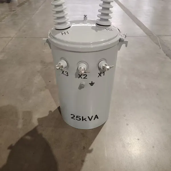
 Single Phase Oil Immersed Transformer 10KVA 15KVA 25KVA 37.5KVA Standard CompliantNegotiableMOQ: 2 Units
 -
Electrical Arc Furnace Transformers up to 120MVA - Certified for Steel Industry ApplicationsUS$ 8000 - 10000MOQ: 1 Unit
-
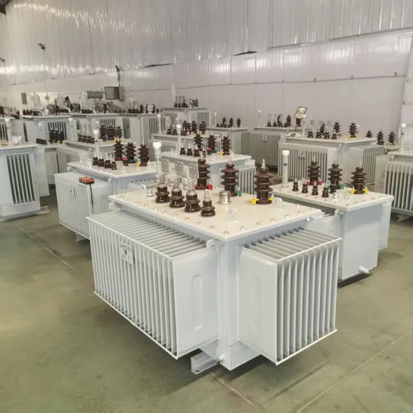
3-Phase Oil Type Transformer 5-Year Warranty With Load Test ReportUS$ 5428 - 5628MOQ: 1 Unit
-
Three Phase Oil Filled Transformer for Mining Operations Dust-Proof DesignUS$ 5428 - 5628MOQ: 1 Unit
-
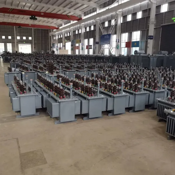
HV Three Phase Oil Filled Transformer With ONAN Cooling 500kVA-2500kVAUS$ 5428 - 5628MOQ: 1 Unit
-
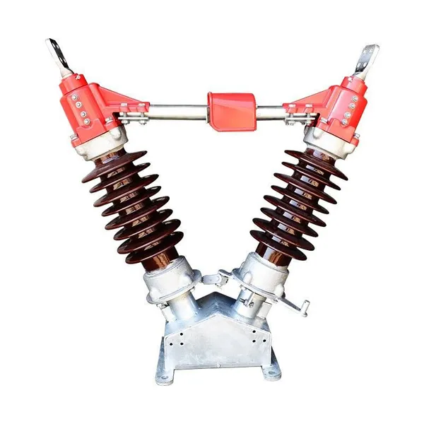
11/24/33KV High Voltage Isolation Switch With Mill Test ReportUS$ 800MOQ: 1 Unit
-
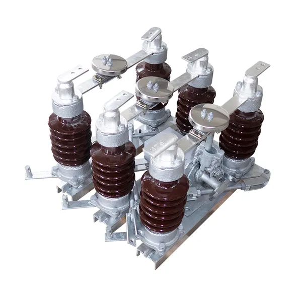
3-Pole Outdoor Isolation Switch With 5-Year Warranty and Compliance TestingUS$ 800MOQ: 1 Unit
-
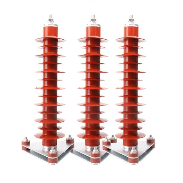
YH5WZ 3KV-110KV Zinc Oxide Arrester for Power Station Outdoor High Voltage DistributionUS$ 21MOQ: 100 Units
-
Outdoor SF6 Load Break Switch LW30-72.5/1250A 24KV 630A 16KA Three PhaseUS$ 10000MOQ: 1 Unit
-
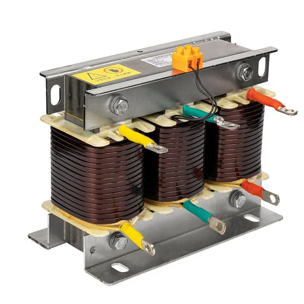
Input Line Reactor for CNC Machine Frequency Converters, 400V 60HzUS$ 65MOQ: 5 Units
-
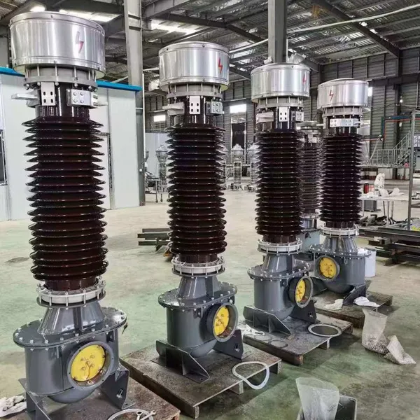
Industrial Grade 35-220KV Oil-Immersed Current Transformer for SubstationsUS$ 480 - 500MOQ: 3 Units
-
LZZBJ9-20 Indoor 24kV High Voltage Cabinet Single-Phase 5-20 for Industrial Power SystemsUS$ 250MOQ: 3 Units
-
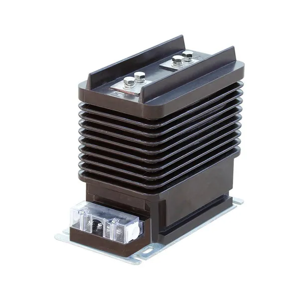
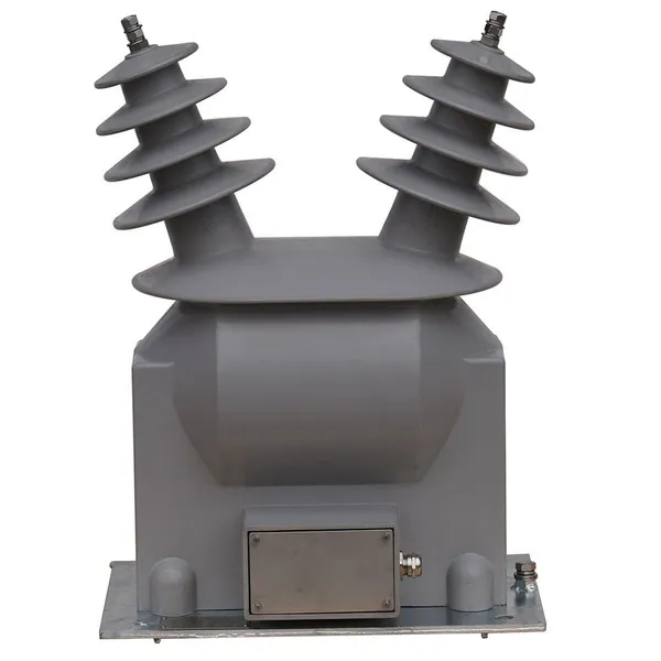
17.5 KV Full-enclosed Outdoor Epoxy Resin Casting and Double Pole Insulated Voltage TransformerUS$ 90 - 100MOQ: 1 Piece
-
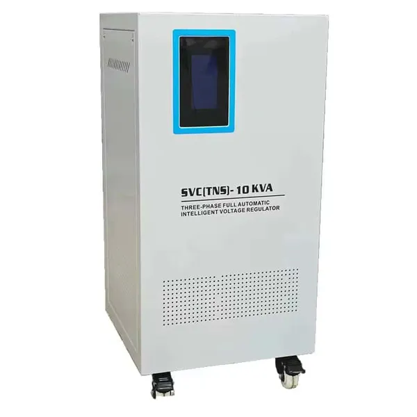
Three Phase 30kVA SVC Voltage Regulator for Textile Manufacturing, Stable OutputUS$ 159MOQ: 10 Units
-
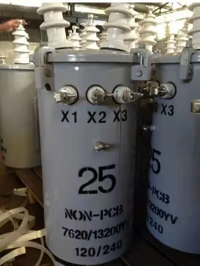
Amorphous Core 25kVA Transformer Compliant With IEC Standards for Power DistributionUS$ 1300 - 2900MOQ: 2 Units
-
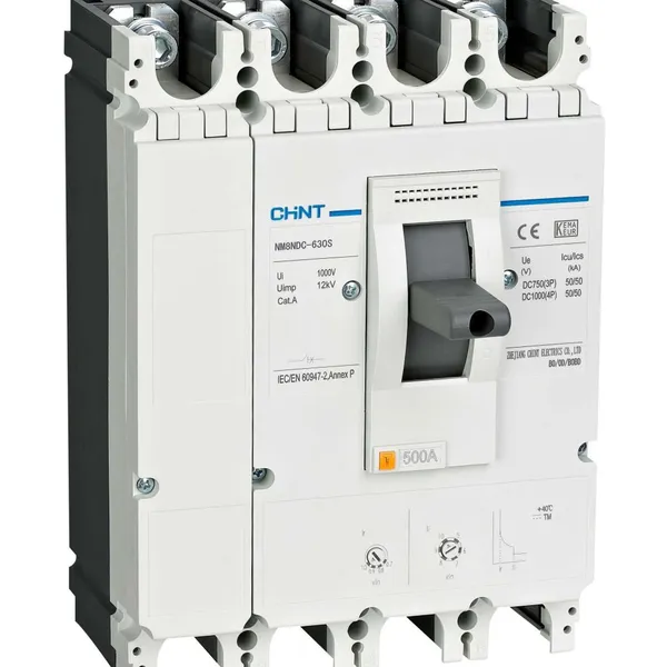
CHINT NM8NDC-630 DC 1000V/Ui High-Voltage Circuit Breaker With 630A Frame CurrentUS$ 425 - 625MOQ: 100 Units
-
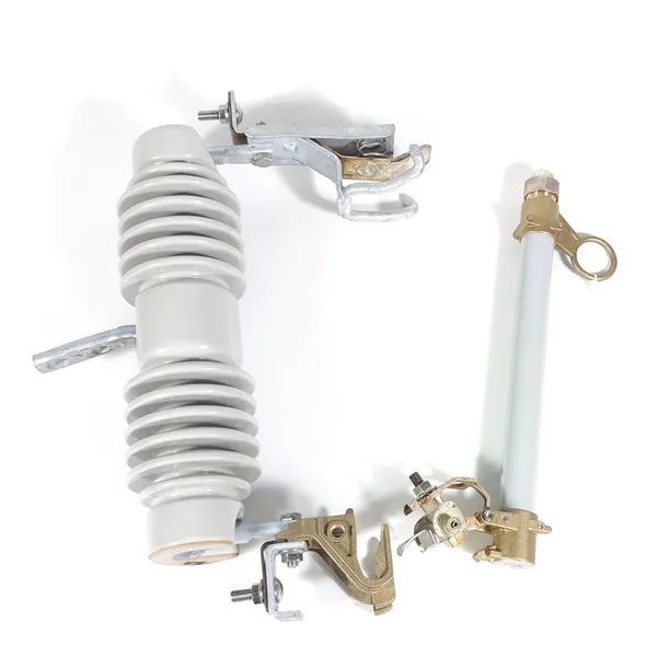
High Voltage Drop Out Fuse Cutout 33KV 27KV 24KV for Overhead LinesUS$ 35MOQ: 100 Units
-
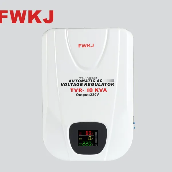
TVR-10 KVA Automatic Voltage Stabilizer 220V ±0.5% Accuracy for Laboratory InstrumentsUS$ 103 - 123MOQ: 1 Unit
-
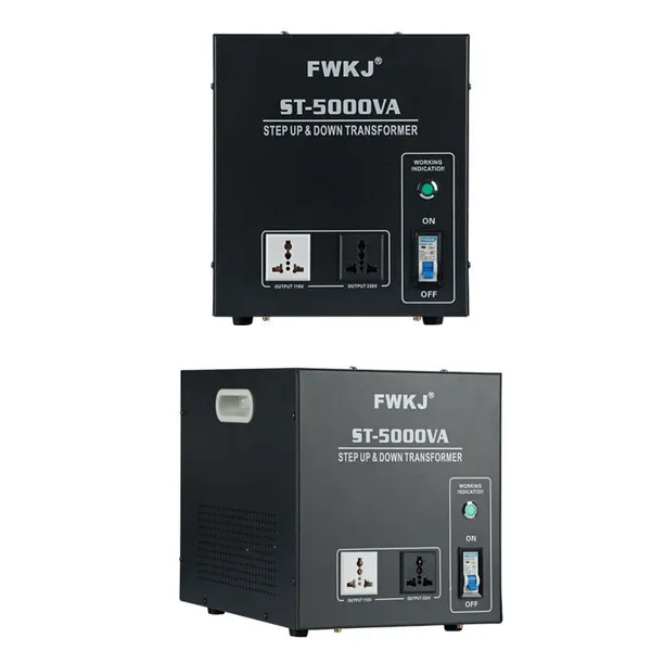
Universal 5000VA Voltage Transformer for International Appliances 110V-220VUS$ 102 - 107MOQ: 10 Units
-
500kV Three-Phase Oil-Immersed Auto Transformer 250MVA for Power GridsUS$ 800 - 9000MOQ: 1 Unit